

 MENU
MENU
In spectroscopy, it is often desirable to use multiple light sources simultaneously—whether to investigate interference effects, calibrate a spectrometer, or generate more complex light spectra. Different light colors or laser sources can be combined to create new measurement scenarios and specifically excite certain spectral ranges. Such experiments make it possible to observe interactions between different light sources, increase the accuracy of measurements, or optimize the analysis of specific materials.
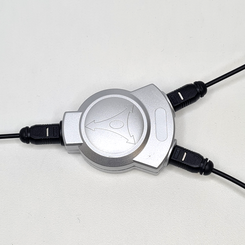
Splitter for Toslink optical cables
However, this does not necessarily require expensive optical components: commercially available Toslink splitters, which we already use for our DIY spectrometers, make it very easy to split and combine light signals. This allows multiple light sources to be used in parallel without the need for complex beam splitters or special optics. Such solutions are robust, cost-effective, and easy to integrate into existing experimental setups, making them particularly attractive for teaching and research institutions.
A fiber optic splitter enables two basic applications:
By cascading several splitters, it is even possible to combine multiple light sources. A simple trick for adjusting different intensities: when a signal is transmitted over longer optical fibers, it weakens, allowing the sources to be easily matched. Toslink optical fibers, for example, are also available in lengths of up to 10 m, which cost only slightly more than the shorter versions.
In addition to fiber optic splitters, there are also switches that allow you to choose between multiple light sources. Such switches make it possible to switch individual light sources on or off without having to change the entire optical cabling. For example, you can switch between a UV LED for fluorescence measurements, a red laser diode for absorption studies, and a white LED for transmission spectra.
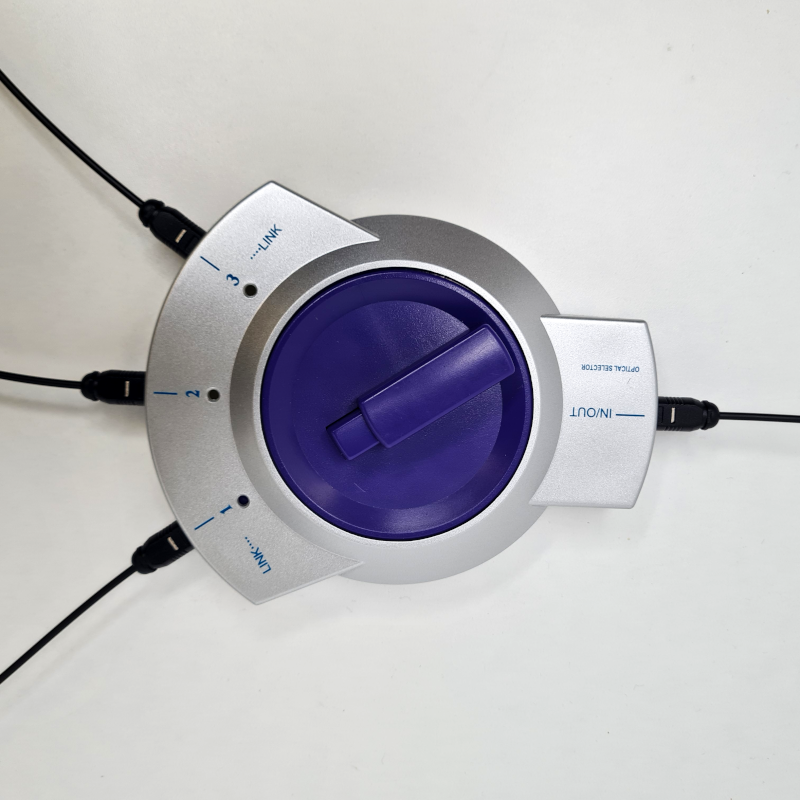
Switch for Toslink optical fibers
More complex measurement setups also benefit from this: In a plant research experiment, for example, a blue light source could first be activated to stimulate chlorophyll, and then switched to a red light source to observe the photosynthesis rate. Such switches make the experiment flexible, save time, and allow the light spectrum to be quickly adapted to the respective requirements—all without expensive mechanical components or complex rewiring.
Of course, it should be mentioned that both the fiber optic splitters and the fiber optic switches lead to losses in the amount of light transmitted. In low-light applications, this can quickly become a problem. For many experiments in teaching, however, the existing intensities of the light sources are usually sufficient to compensate for these losses by extending the integration time of the detector in the spectrometer.
Fiber optic splitters can be used specifically for the calibration of spectrometers. A particularly practical scenario is the superposition of three laser diode modules (e. g., 405 nm, 520 nm, 652 nm), whose sharp emission lines then serve as reference lines. Modules with these wavelengths are now quite inexpensive to obtain because they are used in laser pointers, among other things.
With the aid of two splitters, the three laser beams are guided into a single fiber optic cable and thus coupled into the spectrometer simultaneously. The resulting spectrum shows the three individual peaks.
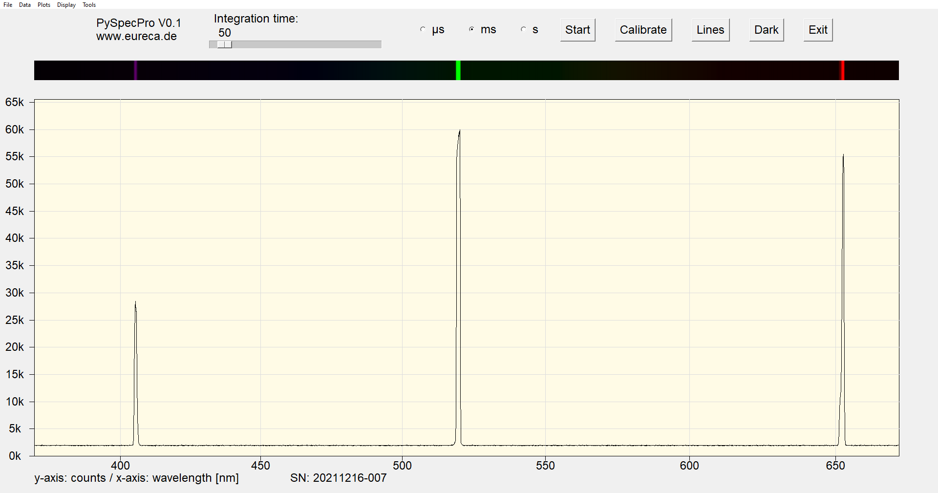
Spectrum with three superimposed laser lines
The spectrum above was generated using our DIY spectrometer in a Czerny-Turner configuration with a 10 µm slit, f = 150 mm focal length, 600 lp/mm grating, and e9u-LSMD-TCD1304-STD line scan camera.
Laser diodes react to temperature fluctuations: The peak wavelengths therefore shift slightly depending on the temperature (typically a few tenths of a nanometer per degree). It therefore makes sense to first measure and record the position of the peaks at a defined room temperature. These reference values then serve as a starting point for initial rough adjustment and calibration, even if the laboratory temperature differs from the original room temperature. Additional stable reference sources, such as emissions from a neon glow lamp, are then used to calibrate the spectrometer to maximum accuracy.
For universities or schools, superimposing multiple light sources provides a particularly vivid demonstration example. Students can immediately see in the spectrum how individual LEDs or laser lines superimpose each other to create a more complex overall spectrum. This makes the abstract concept of the spectral composition of light very tangible.
The experiment is ideal for teaching experiments on spectral analysis, color theory, and laser spectroscopy. For example, it can be used to show why a certain color mixture appears »white« in the visible range, even though it actually consists of individual sharp spectral lines. Differences between narrow-band light sources (laser diodes) and broader-band LEDs can also be easily understood in this way.
In addition, the example provides a practical illustration of how spectrometers are used in research: not only to examine individual light sources, but also to analyze combinations, as often occur in real-world applications. This makes the setup an ideal introductory experiment that teaches the basics and encourages independent thinking.
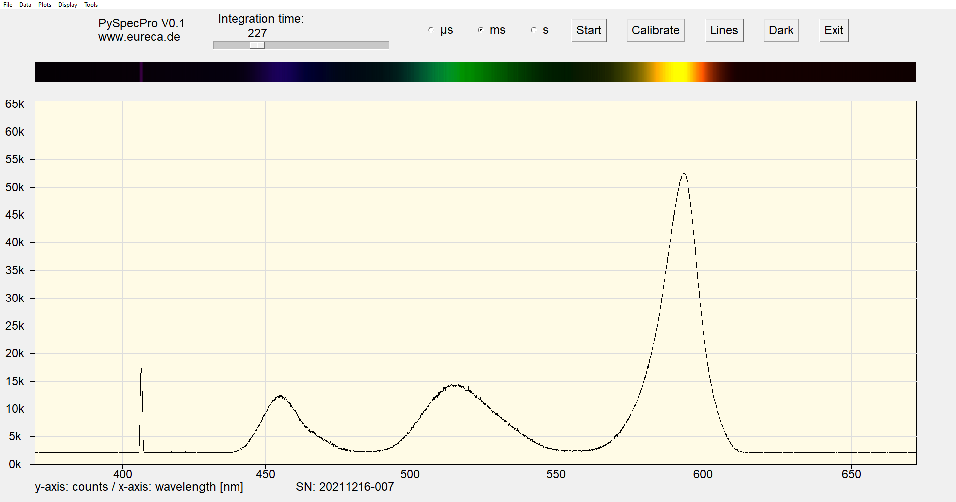
Superimposed spectra of three LEDs (blue, green, and yellow) and a violet laser diode with 405 nm
Using a fiber optic splitter, we have coupled the emission of a red laser diode into the spectrum of a neon glow lamp. At first glance, the spectrum appears to be a typical neon spectrum with its numerous sharp lines. However, upon closer inspection, it becomes apparent that a single line does not fit into the familiar pattern.
As part of an experiment, pupils or students can now be given the task of identifying the »incorrect« signal. This not only allows them to practice assigning emission lines to a specific element, but also sharpens their eye for deviations in experimental data. It is precisely these kinds of questions that make the difference between pure reading and genuine analytical skills.


Excerpt from the spectrum of a neon glow lamp. Once in the original (A) and once with an additional laser diode line (B).
The method can also be expanded: instead of a red laser diode, an LED of a different color could be mixed in, several foreign lines could be accommodated at the same time, or even weak lines could be hidden in the background. Depending on the level of difficulty, teachers can adapt the experiment so that both beginners and advanced spectroscopy »professionals« are challenged.
In the end, the same exciting question always arises: Who can identify the »foreign« line in the spectrum—and how reliable is the assignment? It is precisely this playful approach that makes the search game an ideal exercise that is fun and at the same time deepens understanding of how spectrometers work and the importance of reference spectra.
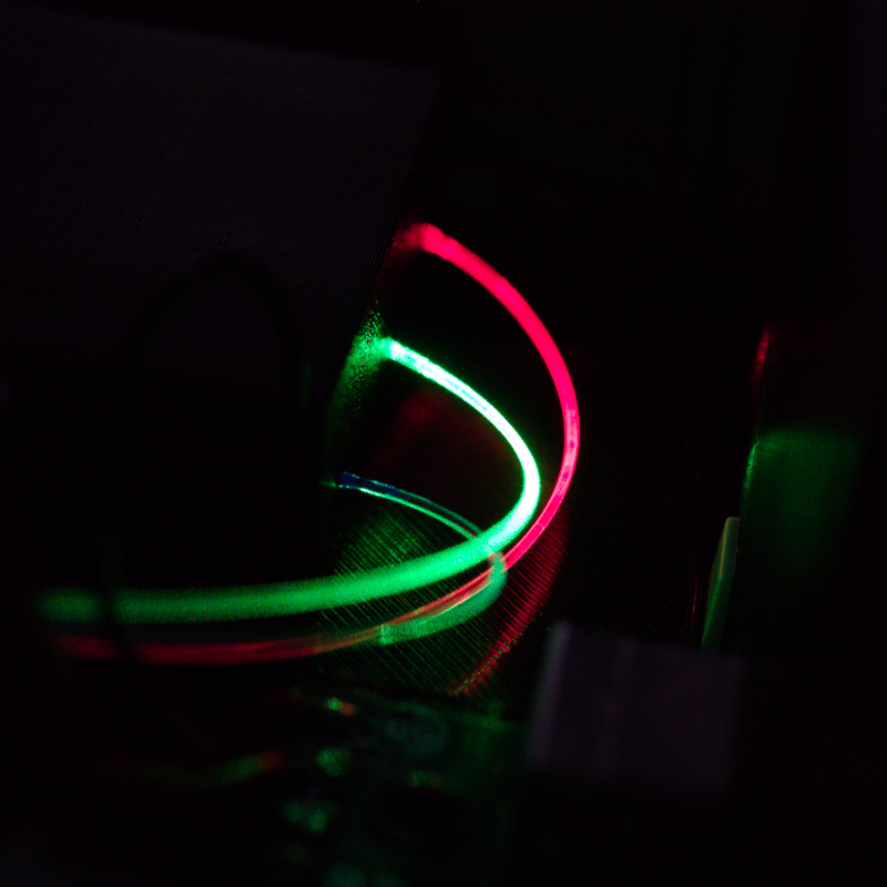
In addition to using commercially available TosLink splitters, with a little DIY skill, you can also build your own small device for superimposing light sources.All you need are uncoated plastic light guides (available by the meter) and 3D-printed mounts to attach individual pieces of light guide to the light sources and then precisely combine them to form a common output for the light guide to the spectrometer.
With these simple tools, you can, for example, combine three laser diode lines into a compact superimposition setup – as shown in the first spectrum above.Such a device is also shown in the first image on this page.
Kit in planning: Eureca will soon be offering a small kit that allows you to easily assemble such a superimposition device for three laser diode lines yourself.If you are interested, you can follow us on LinkedIn or subscribe to our newsletter to stay informed.
 Would you like to replicate the experiment—in your laboratory or teaching environment? Feel free to contact us—we will assist you with planning, setup, calibration, and selecting the right components. Eureca offers advice based on many years of expertise in optoelectronics, optics and spectroscopy—from DIY setups to OEM solutions. Feedback is expressly welcome: Please share your experiences, results, or suggestions for improvement with us.
Here you can easily ask a question or inquiry about our products:
Last update: 2025-10-31

EURECA Messtechnik GmbH
Deutz-Kalker Straße 35, D-50679 Köln
![]()
![]() Phone: +49 (0)221 952629-0
Phone: +49 (0)221 952629-0
Fax: +49 (0)221 952629-9
info(at)eureca.de
www.eureca.de


