

 MENU
MENU
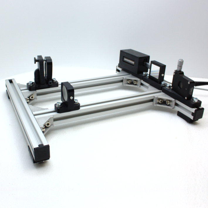
We present application examples for our e9u-LSMD-TCD1304-STD line scan camera in a loose sequence. We use a system of aluminum profiles and 3D printed parts to encourage people to replicate and experiment. Inexpensive, but sufficiently stable replicas are possible with this and the optical components, built into individual modules, can still be finely aligned and adjusted to each other.
An example of this is the Czerny-Turner spectrometer pictured here.
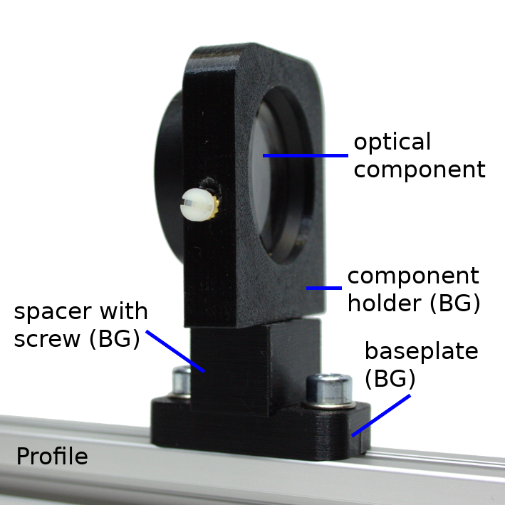
The picture on the right shows the basic structure of a module from which the experiments are assembled.
As a rule, such a module consists of several building groups (BG), which can be used repeatedly in different modules. Basically, a module is made up of a baseplate and the component holder, optionally supplemented by a spacer (as in this picture) or another auxiliary assembly.
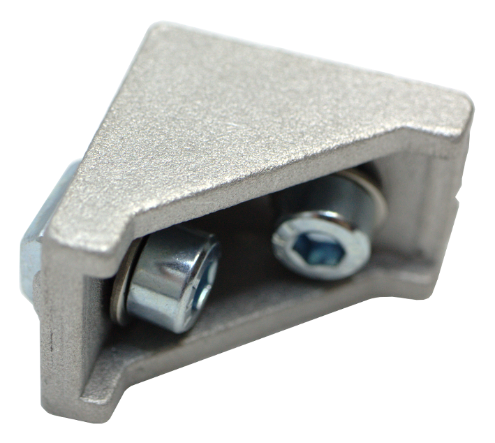
We use aluminum profiles as the basis for the superstructure, such as those used in mechanical engineering or the solar industry. From such profiles, very stable frames can be built using corner connectors, on which the optical components, embedded in modules, are then attached.
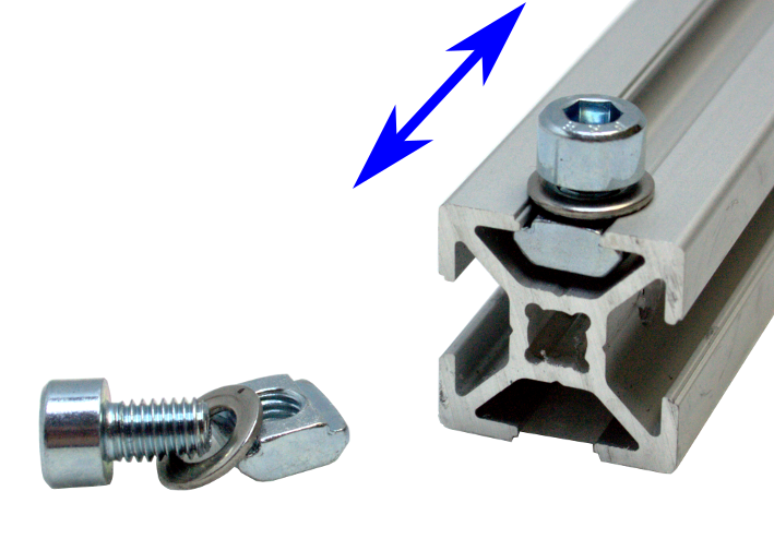
The corner connectors and the modules are fastened with slot nuts, which are pushed into the groove of the aluminum profiles and fixed with a screw. This allows the modules to be freely positioned along a profile, which can then be used to adjust optical path lengths, for example.
Suitable aluminum profiles are available from various suppliers with different widths. We opted for profiles measuring 20 × 20 mm and slot nuts with an M5 thread. Other profiles are possible as well. It should be noted, however, that the profiles may have slightly different cross-sections depending on the manufacturer, so that the slot nuts from one manufacturer do not necessarily have to fit into the profiles from another manufacturer!
Disturbing reflections can occur on metallic or reflective surfaces, depending on the structure. However, we have not yet observed this in practice in our application examples. In the case of very critical applications, the profiles can optionally be sprayed with matte black paint and matching black fastening screws can be used.
In order to make it easier to replicate our application examples and also to enable a high degree of flexibility for various custom structures, we use components from the 3D printer.
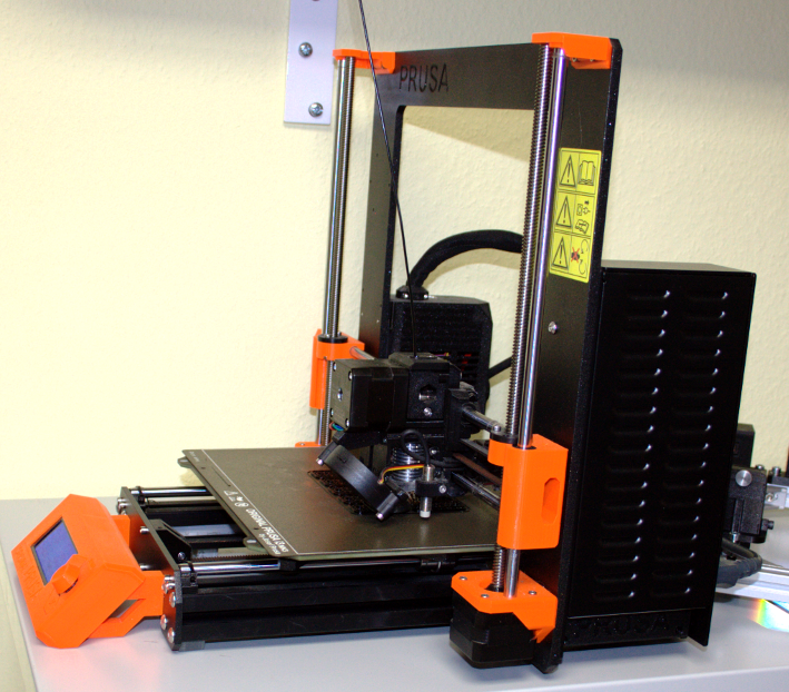
The printing of these components in our examples is carried out with a Prusa i3 MK3 using black PLA filament. In tests conducted to date, PLA has proven to be sufficiently temperature and dimensionally stable in the laboratory. However, if structures are to be used under more severe conditions, the possible need for a different printing material should be considered.
The focus of the component design is on the simplest possible structure, so that modifications are easily possible. The corresponding FreeCAD or STEP files will be available for download on our website in the future.
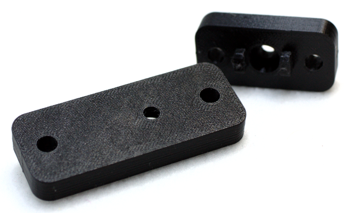
Baseplates, available in different lengths and widths, are used to attach the modules to the aluminum profiles. These are fastened to the profiles with the help of the slot nuts and can – as long as they are not yet fixed with the screws – be moved along the profiles for adjustment purposes. After the adjustment, the screws of the slot nuts are tightened.
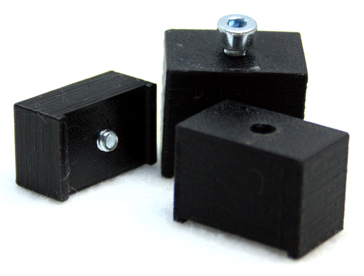
In order to change the height of the component holders above the aluminum profiles, if necessary, spacers in different heights are used. Changes in height may be necessary, for example, if individual larger or higher components are to be used in the optical design.
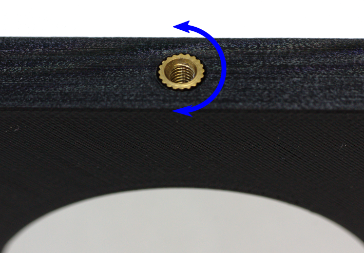
The components are attached to each other on the baseplates, for example, using M3 thread inserts. These are sunk and fixed in the holes provided for this purpose in the 3D printed parts, for example with a soldering iron or a special sealing aid. After cooling down, the thread inserts are then firmly seated in the PLA components.
After screwing in, the components can still be rotated around the axis of the fastening screw in order to adjust the required angles in the optical structure.
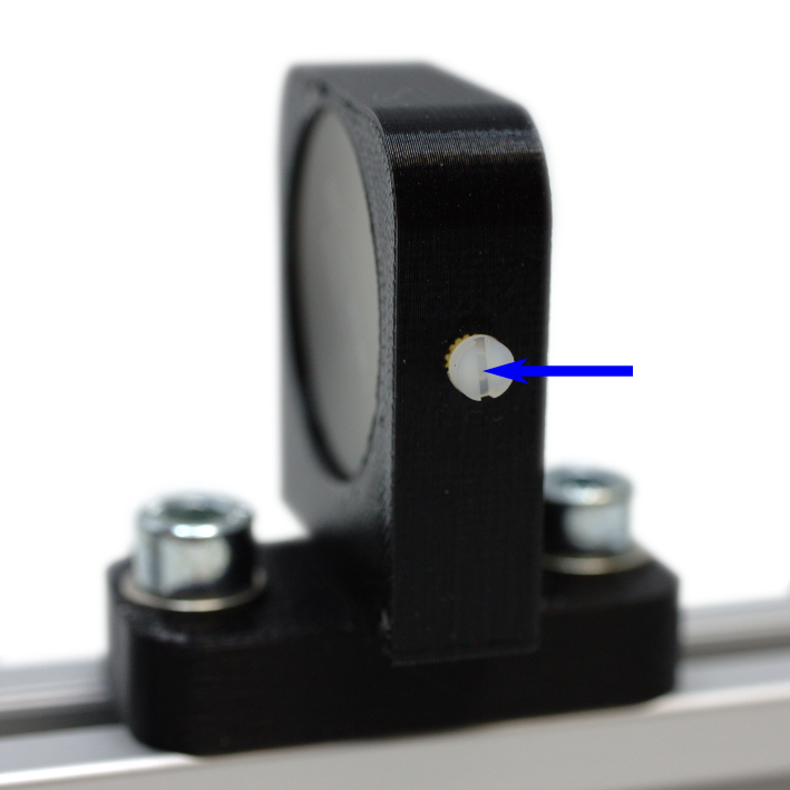
The holders for lenses, mirrors and gratings are designed in such a way that the corresponding components can be inserted without any problems, taking into account the pressure tolerances. To secure them against slipping or falling out, the holders have a lateral M2 thread insert for an M2 nylon screw.
This is sufficient for laboratory use to secure the optical components. However, for use in applications with stronger vibrations, additional securing may be required, for example by gluing.
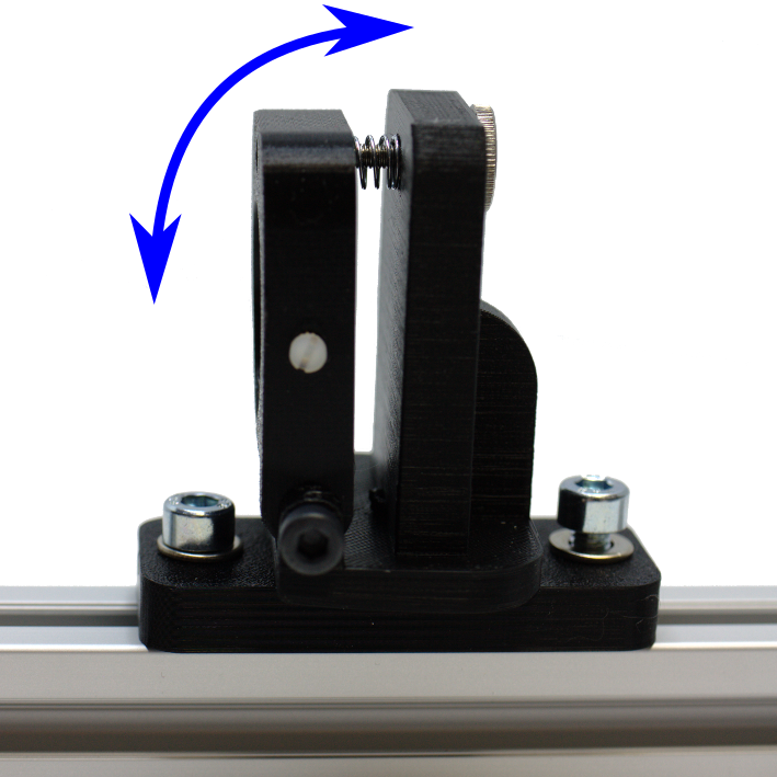
Some component holders can be tilted by a few degrees in the vertical for adjustment purposes. A combination of thread inserts, knurled screws and springs is used for this purpose. This is used in mirror tilting modules, for example.
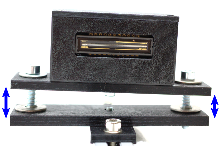
Height adjustments may also be necessary horizontally, for example by tilting the line scan camera in the lower image using springs and screws in order to be able to adapt it to the beam path of the experiment. This picture shows the height adjustment without the cladding, which also serves as a guide and provides support.
You will also find this information handy for printing in this PDF.
Here you can easily ask a question or inquiry about our products:
Last update: 2023-29-03

EURECA Messtechnik GmbH
Deutz-Kalker Straße 35, D-50679 Köln
![]()
![]() Phone: +49 (0)221 952629-0
Phone: +49 (0)221 952629-0
Fax: +49 (0)221 952629-9
info(at)eureca.de
www.eureca.de


